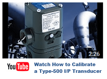
Before using your I/P or E/P transducer, they must be properly calibrated in your system. Such things as orientation, supply pressure, temperature and flow rates could affect the output pressure, especially with the use of any of our 500 series units. Please find the instruction sheets (see section 2) for your unit below. You can also follow along with the quick start guide or watch the video below on how to calibrate your pressure transducer.
Instruction Manuals.
Type 500 instructions
Type 550 Instructions
Type 590 Instructions
Type 900 Instructions
Type 950 Instructions
Calibration Video.

Quick Start Guide for Calibration.
The following quick start calibration guide is for our Type 500 unit.
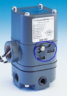
- Open protective covers to expose Zero and Span adjustment screws.

- Make appropriate air supply connections and an accurate pressure gauge to verify calibration results.
- Connect electrical signal and supply the IP or EP with the minimum input signal that corresponds to the lowest psi output range for the unit. IE.. for a 4-20 mA input unit, apply a 4 mA signal to the IP.
- Observe the output pressure and use the “Zero” screw to adjust the minimum output pressure. Turn zero screw counter-clockwise will increase pressure, clockwise to decrease pressure. Please see our calibration guide for proper screw orientation.
- Increase signal to maximum input. IE..for a 4-20 mA unit, apply a 20 mA signal.
- Observe the output pressure and use the “Span” screw to adjust the maximum pressure.
- Repeat steps 3 to 6 in order to verify results. Adjust as necessary.
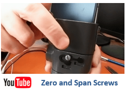
We added a quick video on the zero and span screws to demonstrate what they actually control.
Zero and Span Screw Video.

