Sign up for the ControlAir newsletter.
Get news, updates, and offers direct to your inbox.
 Several models of I/P transducers utilize a small orifice to reduce the pressure in the internal pilot chamber. These orifices can range in size from 0.020” to 0.090”. In order to produce consistent, accurate pressure regulation this orifice must remain clear of debris. This post will act as a quick guide on cleaning that orifice in the case that your I/P transducer is giving unexpected performance. If the output of your unit is unstable or unexpectedly low, it may be a good idea to check the orifice.
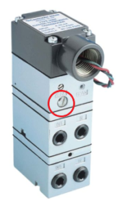
The orifice screw can be found on the body of each I/P transducer. On the Type 550 and Type 900 (shown left) the orifice screw can be found on the face of the unit below one of the calibration screws.
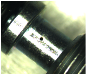
To clean the orifice, first turn off supply air to the unit. Remove the screw using a flat head screwdriver and inspect the screw for any obvious build-up and debris. Remove any present build-up. You will notice a very small hole (below) on the side of the screw. Using a gauge pin or thin wire, run the wire through the hole to clear any internal blockages. If you are using a high output range unit (up to 120 PSI), the orifice size will be approximately 0.090”. You should utilize an appropriately sized gauge pin to clear the orifice. Lower range units (3-15 PSI) utilize an approximately 0.020” sized orifice.
 Once the orifice is cleared, reinstall the screw in the side of the unit. The screw should fit snugly but should not be over torqued to avoid damaging the screw. If air is leaking past the screw when supply air is given to the unit, continue to tighten the orifice screw. For further instruction on troubleshooting a unit, please consult the instruction manual which can be found in the unit’s box or on the product page of the website for each specific unit.