Sign up for the ControlAir newsletter.
Get news, updates, and offers direct to your inbox.
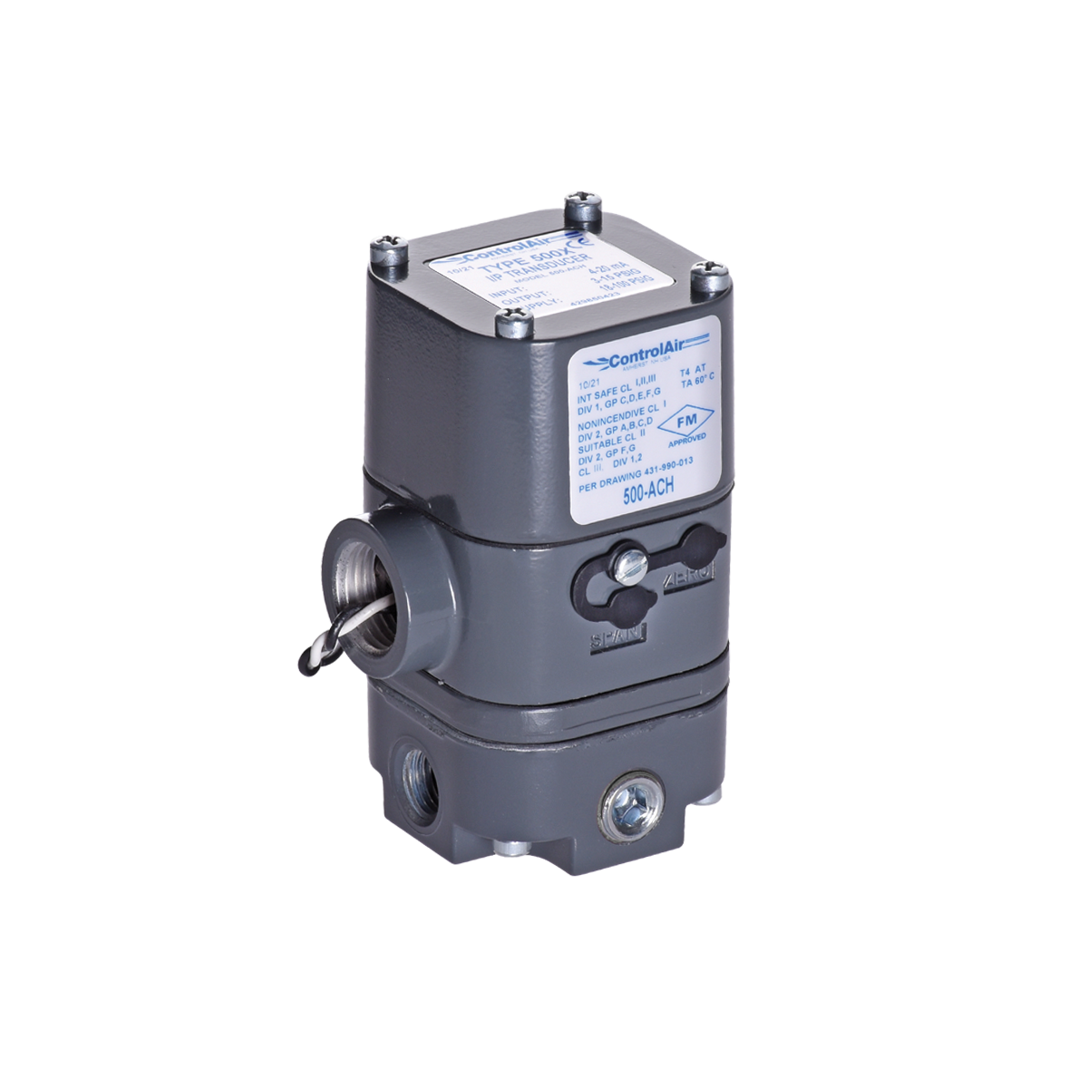
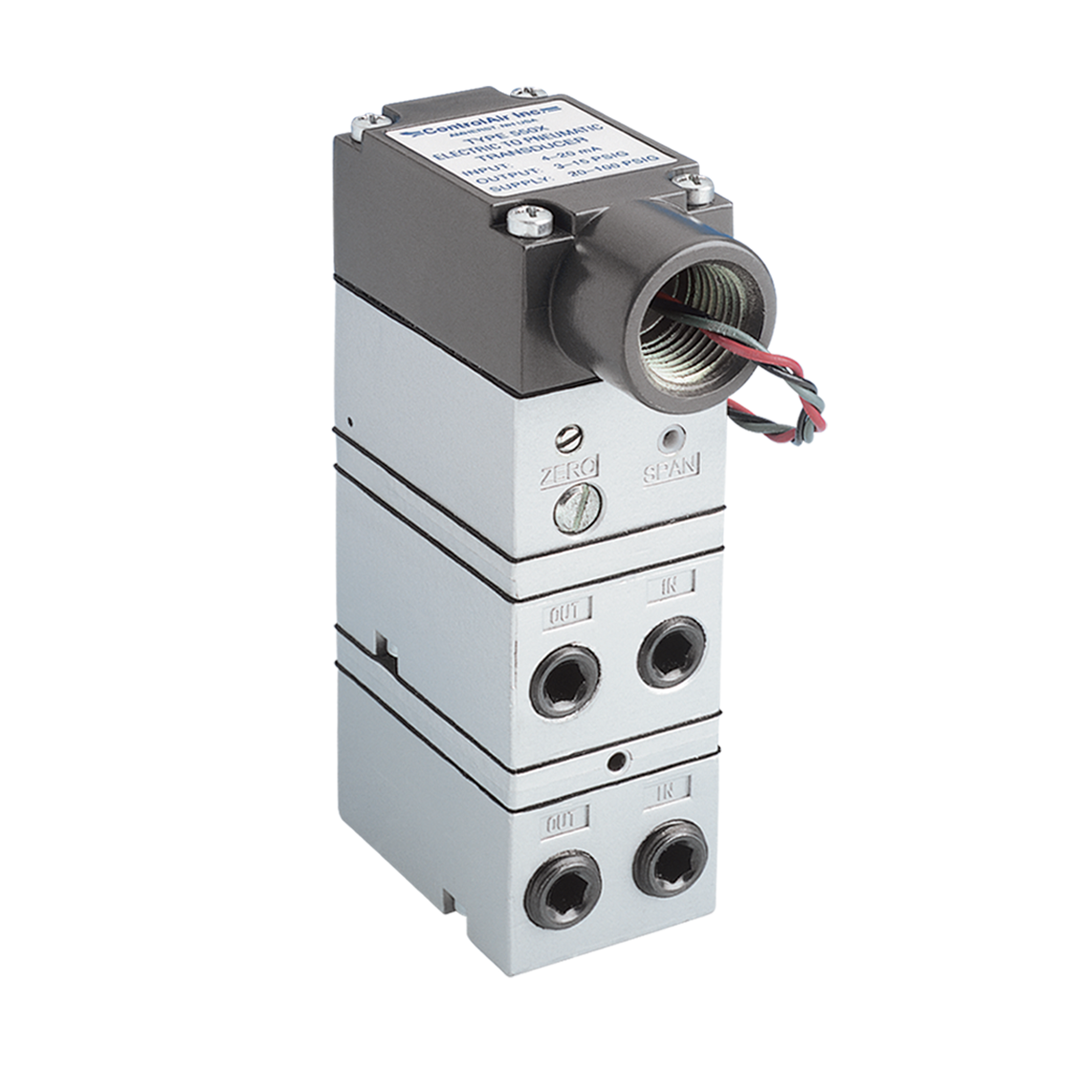
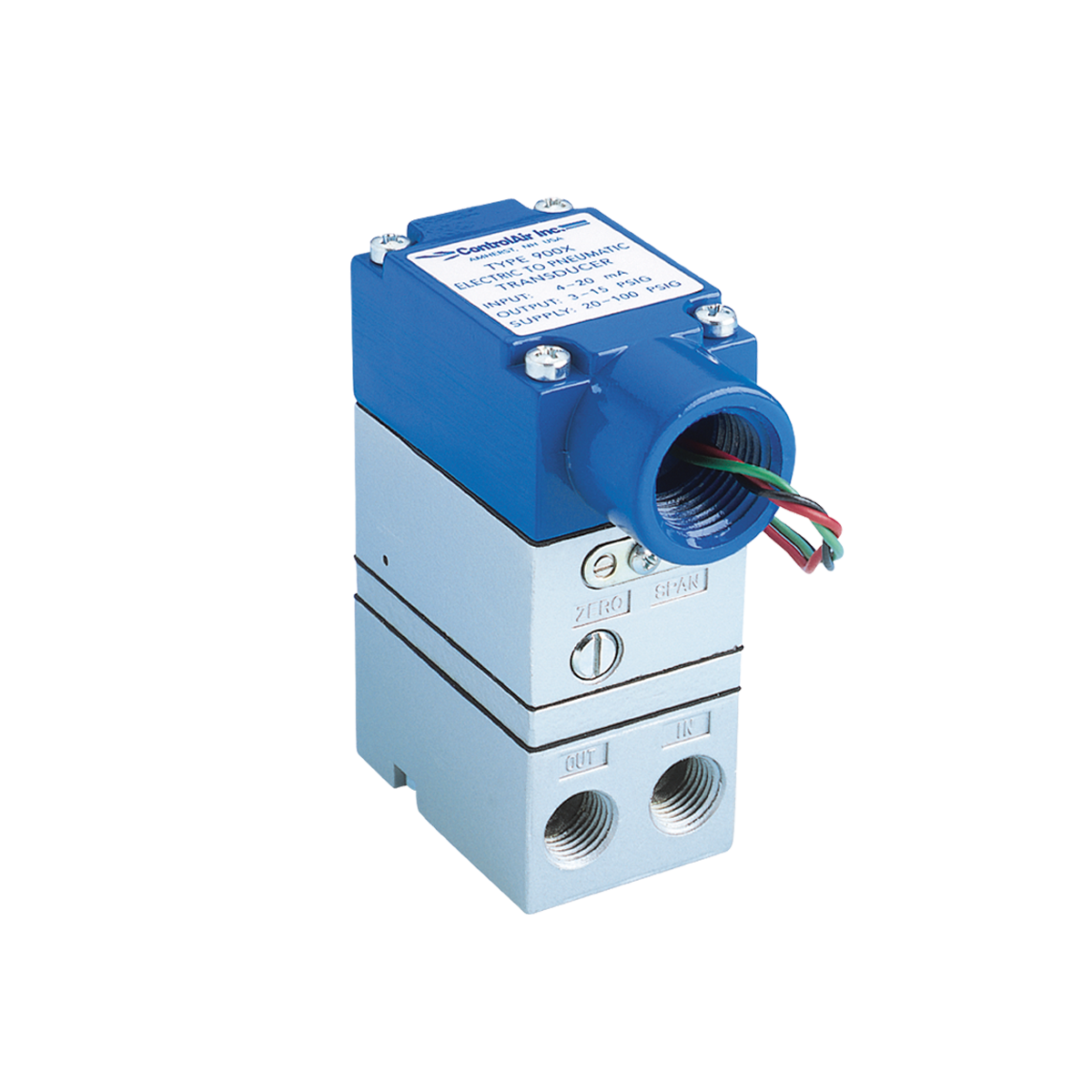
When an I/P transducer loses its electrical input signal, its output pressure depends on the model and pressure range. For the ControlAir configurations discussed here, non-zero-based Type 500, Type 550, and Type 900 units are expected to produce approximately 1.5 psi, while zero-based Type 550 and Type 900 units drop to 0 psi.
These conditions assume that the pneumatic air supply remains available. Losing the electrical signal and losing supply air are different operating conditions.
An I/P, or current-to-pressure, transducer converts an electrical current signal into a proportional pneumatic output pressure. It connects electronic controls to pneumatic devices such as valve actuators and positioners.
A common configuration converts a 4–20 mA input into a 3–15 psig output. Other pressure ranges are available to suit different applications.
The table below summarizes the expected behavior of the ControlAir configurations covered in this article.
| ControlAir Model | Non-Zero-Based Configuration | Zero-Based Configuration |
|---|---|---|
| Type 500 | Approximately 1.5 psi | Not covered in this article |
| Type 550 | Approximately 1.5 psi | 0 psi |
| Type 900 | Approximately 1.5 psi | 0 psi |
Verify the selected model and configuration when determining signal-loss behavior for an application.
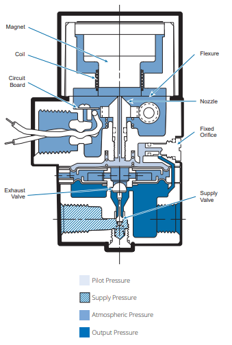
In the non-zero-based units described above, a start-up spring continues to apply force to the supply valve after the electrical input is lost. This allows some supply air to reach the output.
As a result, removing the electrical signal does not necessarily eliminate pneumatic output pressure.
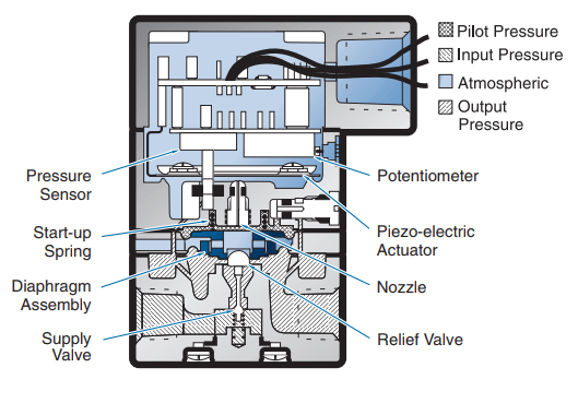
A zero-based I/P transducer has an output range that begins at 0 psig. For example, ControlAir’s Type 550X is available with zero-based ranges of 0–30, 0–60, and 0–120 psig.
Zero-based designs use a negative-bias spring arrangement to provide a true zero-pressure output. The zero-based Type 550 and Type 900 configurations discussed here return to 0 psi when the electrical input is lost.
No. In a 4–20 mA control loop, 4 mA is a valid input representing the bottom of the calibrated range.
For a transducer configured for 4–20 mA input and 3–15 psig output:
This distinction matters when evaluating a low output pressure or troubleshooting an interrupted control signal.
Start with the required electrical input and pneumatic output range. Then confirm the flow capacity, available supply pressure, mounting requirements, and expected output after signal loss.
Explore ControlAir’s Type 500, Type 550X, and Type 900X to compare configurations and access product specifications.