

Sign up for the ControlAir newsletter.
Get news, updates, and offers direct to your inbox.
A first-cut regulator performs the initial pressure reduction from a high-pressure source. The term describes its role in the system rather than a universal pressure range or accuracy rating.
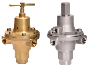
For example, ControlAir’s Type 3500 and Type 3600 accept inlet pressures up to 6,000 psig and offer selectable outlet ranges through 0–225 psig. Those ratings apply to these models, not to every first-cut regulator.
Supply pressure effect is the change in regulated outlet pressure caused by a change in inlet pressure. It is particularly important when the supply comes from a gas cylinder whose pressure decreases during use.
The direction and magnitude of the outlet-pressure change depend on the regulator’s design and operating conditions. In some unbalanced pressure-reducing designs, outlet pressure can rise as inlet pressure falls.
Do not assume that a percentage change in supply pressure produces the same percentage change in outlet pressure. Review the manufacturer’s supply-pressure-effect data for the selected regulator.
Consider two stages when the source pressure varies widely and downstream equipment requires tighter pressure control than a single regulator can provide.
The first stage reduces source pressure to an intermediate level. The second stage then controls the final delivery pressure while experiencing a smaller change in its own inlet pressure.
A balanced-valve design can also reduce sensitivity to supply-pressure changes. The appropriate arrangement depends on the required pressure stability, available supply pressure, and flow demand.
Select the intermediate pressure to provide sufficient inlet pressure for the second regulator under operating flow, while staying within all downstream component ratings.
Identify the highest pressure the regulator may encounter, not just the normal operating pressure. Confirm the ratings of the regulator, connections, gauges, and associated equipment for the intended service and temperature.
Select a spring range that includes the required operating pressure and provides suitable adjustment and control performance.
Avoid treating “twice the desired outlet pressure” as a universal sizing rule. Use the manufacturer’s range-selection guidance and performance data for the specific model.
Establish normal and peak flow demand. Review published flow curves or capacity tables at the applicable inlet and outlet pressures.
Cv helps compare flow capacity, but does not establish whether the regulator will maintain the required outlet pressure. Also check droop, the reduction in outlet pressure as flow increases.
Identify the gas composition and check all wetted materials, including the body, diaphragm, seals, and valve seat.
For corrosive or sour gas service, a stainless steel body alone does not establish compatibility. Confirm the complete regulator configuration against the service conditions and applicable material requirements with the manufacturer.
| Feature | Type 3500 | Type 3600 |
|---|---|---|
| Body Material | Brass | 316 stainless steel |
| Maximum Inlet Pressure | 6,000 psig | 6,000 psig |
| Available Outlet Ranges | 0–30, 0–60, 0–125, 0–150, or 0–225 psig | 0–30, 0–60, 0–125, 0–150, or 0–225 psig |
| Relieving Operation | Non-relieving | Non-relieving |
| Service Consideration | Non-corrosive gases compatible with the complete construction. | Corrosive and sour gas applications, subject to configuration and service verification. |
Review the Type 3500 and Type 3600 product information for complete specifications and ordering options.
Use qualified personnel and follow the regulator’s installation instructions. Keep piping clean, verify flow direction, and monitor inlet and outlet pressure during startup and adjustment.
Evaluate downstream overpressure protection as part of the system design. A pressure regulator should not be treated as a substitute for a shutoff valve or a dedicated overpressure-protection device.
Follow the manufacturer’s venting requirements for the gas being used. Before maintenance, isolate the regulator and safely relieve trapped pressure on both sides.
For model-specific procedures, consult the Type 3500/3600 Installation, Operation, and Maintenance Instructions.
Applications include compressed-gas supplies, pilot-operated regulator systems, industrial gas distribution, oil and gas production, and instrumentation supply systems.
The appropriate regulator and number of pressure-reduction stages depend on the source pressure, gas composition, flow demand, and final pressure-control requirements.
For additional selection guidance, read How to Determine the Appropriate Regulator or contact ControlAir at [email protected] with your application details.